Verify that the subinterfaces are now active.Ĭlose configuration window Part 3: Test Connectivity with Inter-VLAN Routing Step 1: Ping between PC1 and PC3. Therefore, in order to enable subinterfaces, you must enable the physical interface that they are associated with. Subinterfaces are virtual interfaces that are associated with a physical interface.
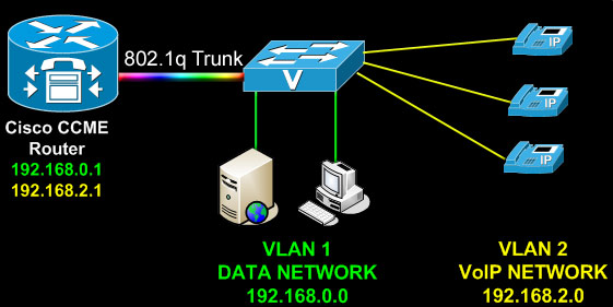
Use the show ip interface brief command to verify subinterface configuration. R1(config- subif )# encapsulation dot1Q 30 R1(config- subif )# encapsulation dot1Q 10 Refer to the Address Table and assign the correct IP address to the subinterface. Set the encapsulation type to 802.1Q and assign VLAN 10 to the subinterface. Part 2: Configure Subinterfaces Step 1: Configure subinterfaces on R1 using the 802.1Q encapsulation. The PCs are on different IP networks and require a router or a L ayer 3 switch to provide communication between them. Were the pings successful? Why did you get this result? Issue the show vlan brief command to verify VLAN configuration.ġ default active Fa0/1, Fa0/2, Fa0/3, Fa0/4Ĭlose configuration window Step 3: Test connectivity between PC1 and PC3. S1(config- if)# switchport access vlan 30 S1(config- if)# switchport access vlan 10 Assign the port connected to PC3 to VLAN 30. Assign the port connected to PC1 to VLAN 10.
Configure interfaces F0/6 and F0/11 as access ports and assign VLANs.S1(config- vlan )# vlan 30 Step 2: Assign VLANs to ports. Instructions Part 1: Add VLANs to a Switch Step 1: Create VLANs on S1. You will then enable trunk interfaces and verify connectivity between VLANs. In this activity, you will configure VLANs and inter-VLAN routing. Part 3: Test Connectivity with Inter-VLAN Routing Scenario